
Posted on: July 28, 2025
What is PPA optimization ?
RTL designers who write HDL code to design a circuit do not only have to fulfill the functional verification, the designer needs to meet the specifications given by vendors of 3 respective metrics : Performance, Power and Area (PPA) !
- Performance - Maximum operating frequency capacity of the chip (i.e. DUT for FPGA) (This is the most critical spec)
- Power - Consume minimal dynamic and static power
- Area - Take the least area on the given chip area (i.e in terms of FPGA: least amount of Logic and memory resources such as LUT, FF, etc)
In this blog we show an example of PPA optimization of RTL design on FPGA
Let us take an RTL design of an unsupervised learning engine that implements spike timing dependent plasticity (STDP) training from a brain-inspired neuromorphic AI accelerator designed by Liu et al. (2019). The details of the STDP learning rule and how the learning engine design functions is explained in this blog STDP learning engine.
A Brief Intro to STDP
Spike-Timing-Dependent Plasticity (STDP) is a learning rule inspired by how the human brain works. It changes the weight strength between a pair of neurons based on when they fire. If the presynaptic neuron fires just before the next layer postsynaptic one, the connection gets stronger. But if it fires after, the connection becomes weaker. This helps spiking neural networks (SNNs) learn patterns that happen over time, similar to how our brain processes information. Because of this, STDP is useful in building energy-efficient on-chip trainable AI-computing systems for things like real-time learning, robotics, and edge devices.
A visualization of STDP weight update mechanism between 4 pre-synaptic and 1 post-synaptic neuron
Unsupervised Learning Engine Block Diagram
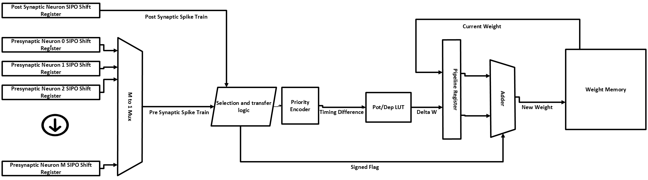
Below is the block diagram of a circuit design that implements spike-timing-dependent plasticity training in a brain-inspired AI accelerator.
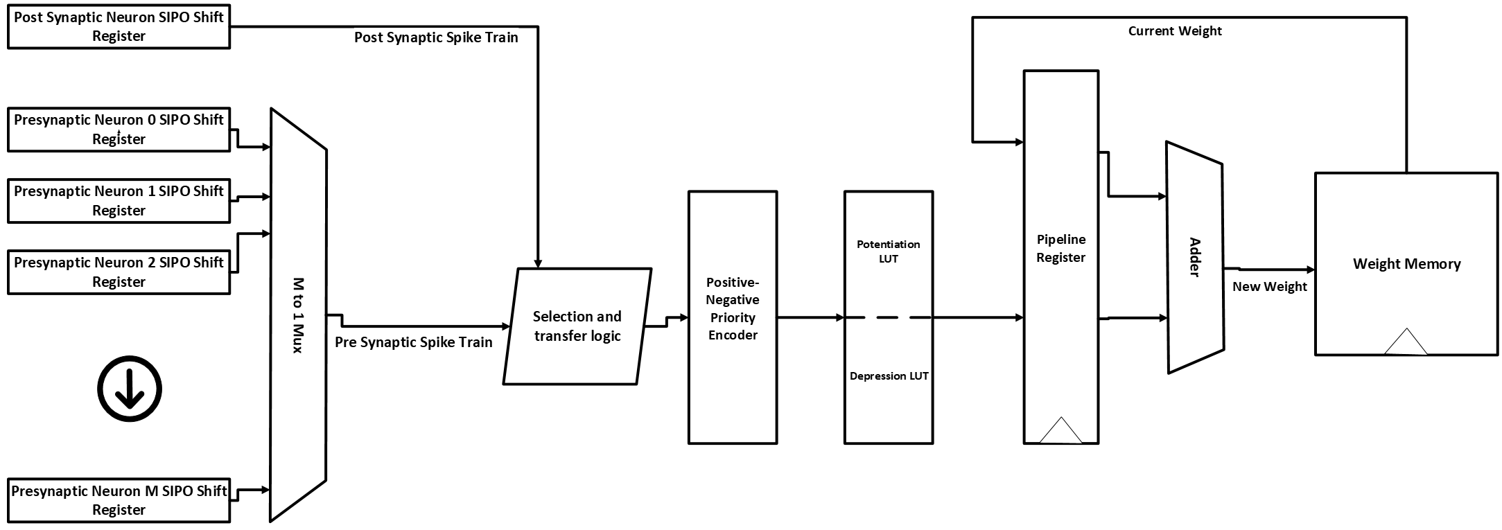
Block-level RTL diagram of STDP learning logic integrated into a neuromorphic accelerator
Since the function of the circuit was explained in details in the blog mentioned before, we are only going to focus how can a simple PPA optimization be done for such a circuit. The SystemVerilog RTL code of the entire learning engine architecture along with it's testbench has been attached to this github repository link .
Inspection steps for PPA optimization on FPGA
Here are the sequential steps how we should inspect an existing design for PPA optimization :
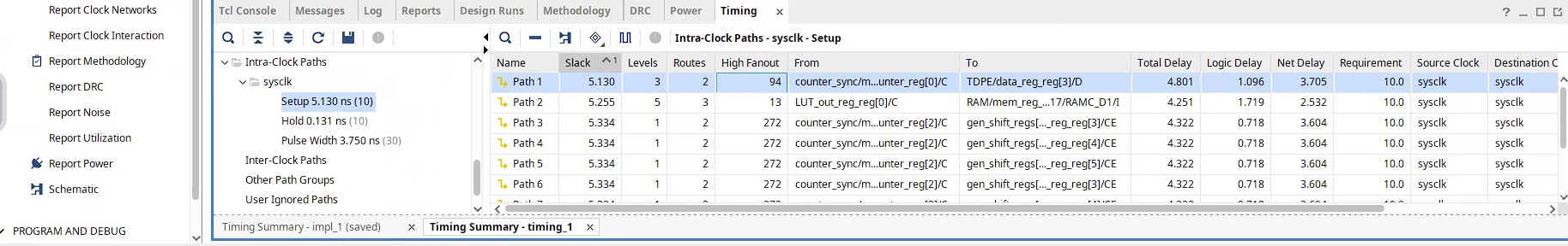
- Performance: Performance means the maximum operating clock frequency that the design can run. It determines design's processing speed and generally the most important spec that must be met as provided by the Vendor. We can find out the approximate maximum operating frequency \(F_{max}\) from the Vivado timing report. Let us check the screenshot from the implementation timing report of the current learning engine design in the following :
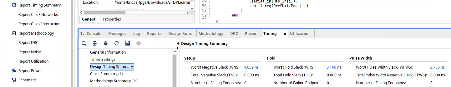
Here the Fmax is approximated by using the equation \(F_{\text{max}} \approx \frac{1000}{T_{\text{clock}} - \text{WNS_Setup}}\)=187.23 MHz in MHz where we used \(T_{\text{clock}}\)=10ns as the base system clock was chosen 100 MHz.
Now the maximum clock frequency or \(F_{max}\) of a design spec mainly depends upon the longest delay path i.e. critical path from the design.We can express the \( F_{\text{max}} \) using the timing components of a typical synchronous digital design as follows:
$$ F_{\text{max}} = \frac{1}{ T_{\text{clk-q}} + T_{\text{logic}} + T_{\text{routing}} + T_{\text{setup}} - T_{\text{skew}} } $$Assuming \( T_{\text{skew}} \)=0 and grouping the other delay terms into a single critical path delay \( T_{\text{critical-path}} \) , we can rewrite the equation as:
$$ F_{\text{max}} = \frac{1}{ T_{\text{critical-path}} } $$ Now let us analyze the critical path of this design using the Vivado Timing Summary. The screenshot below highlights the setup timing, which is the most critical delay component in synchronous designs.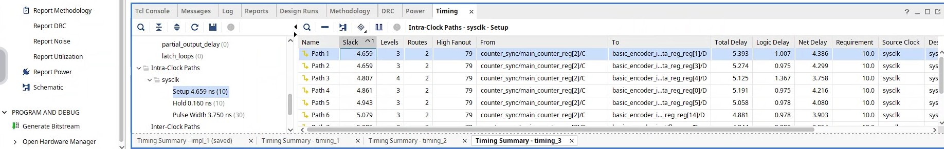 According to the report, the longest datapath delay—measured at 5.393 ns—spans from the input port (counter index) to the priority encoder logic. Reducing this critical path delay will result in increasing the maximum operating frequency, enabling the circuit to operate with higher processing speed.
 - Area In general perspective, Area refers to the amount of hardware resources consumed by RTL implementation on the target FPGA device. Specifically, for FPGA area measuring, we analyze the major component counts such as LUT, FF/Registers, BRAM and DSP blocks. Now let us have a look at our current resource usage from Vivado utilization report :
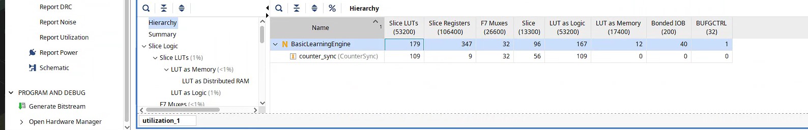
From the report, we observe that the design utilizes 179 LUTs and 347 flip-flops, which are the primary contributors to logic resource usage in this implementation of the STDP learning engine since no BRAM or DSP are being used.
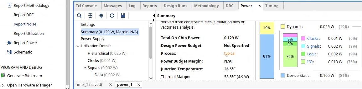
- Power Power optimization in FPGA design aims to reduce both dynamic and static power consumption while maintaining required performance and functionality. The power consumed due to switching activitiy within the programmable logic blocks and their interconnect is referred mainly as dynamic power whereas the power consumed due to leakage current within the transistor components is known as static power. Let us have a look at the following screenshot from Vivado implementation power report where we see dynamic power is about 25 mw and static power consumption is about 105mw:
There are different ways to reduce power consumption in RTL design for FPGA such as reducing the number of resources by optimizing RTL modules, replacing the CLB logic based designs with vendor provided optimized IPs, enabling a specific submodule only when it is needed to operate, clock gating etc.
Let’s Dive In and do a PPA Optimization for the STDP Learning Engine !!
As discussed earlier, performance is usually the most critical metric in design optimization. But to build a truly efficient system, we must also keep a close eye on area and power. Let’s now work on a step-by-step PPA optimization of our design.
Performance Optimization
Notice during the inspection the Vivado showed the maximum critical path delay of 5.393ns is from the input to the priority encoder datapath. Now if we can reduce this delay then we can achieve higher \(F_{max}\) as shown by the direct reciprocal relationship equation before !
Please read the details of the function of the STDP learning engine and how it implements STDP learning has been well explained in this blog, to understand the authors structure and mechanism. In brief, in order to determine the timing difference of the presnaptic vs post-synaptic spike events, the authors use two sets of priority encoder combined in one module that generates positive or negative timing difference to inform the learning engine whether to strengthen or weaken the existing weights. The RTL code for the priority encoder in the neuron’s learning engine, which records spike events from the current neuron and its presynaptic neurons over the past 16 timesteps by storing them in shift registers, is presented as follows:
always_ff @(posedge clk) begin
    if (rst) begin
        data_reg <= 16'b0;
        flag <= 1'b0;
        LUT_out_reg <= 20'b0;
    end else begin
        if(Post[15]==1) begin
            data_reg <= Pre;
            flag <= 1'b0; // Post-synaptic neuron is active, set flag to 0
        end
        else if (Pre[15] == 1) begin
            data_reg <= Post;
            flag <= 1'b1; // Pre-synaptic neuron is active, set flag to 1
        end
        else begin
            data_reg <= 16'b0; // No active neuron, reset to zero
            flag <= 1'b0; // Reset flag
        end
        // Update LUT output register
        LUT_out_reg <= LUT_out; // Store LUT output in register
    end
end

always_comb begin
    if(flag) begin
        unique casez(data_reg)
            16'b1???????????????: TimingDifference = 6'sd0;
            16'b01??????????????: TimingDifference = 6'sd1;
            16'b001?????????????: TimingDifference = 6'sd2;
            16'b0001????????????: TimingDifference = 6'sd3;
            16'b00001???????????: TimingDifference = 6'sd4;
            16'b000001??????????: TimingDifference = 6'sd5;
            16'b0000001?????????: TimingDifference = 6'sd6;
            16'b00000001????????: TimingDifference = 6'sd7;
            16'b000000001???????: TimingDifference = 6'sd8;
            16'b0000000001??????: TimingDifference = 6'sd9;
            16'b00000000001?????: TimingDifference = 6'sd10;
            16'b000000000001????: TimingDifference = 6'sd11;
            16'b0000000000001???: TimingDifference = 6'sd12;
            16'b00000000000001??: TimingDifference = 6'sd13;
            16'b000000000000001?: TimingDifference = 6'sd14;
            16'b0000000000000001: TimingDifference = 6'sd15;
            default:              TimingDifference = 6'sd0;
        endcase
    end else if (!flag) begin
        unique casez(data_reg)
            16'b1???????????????: TimingDifference = -6'sd0;
            16'b01??????????????: TimingDifference = -6'sd1;
            16'b001?????????????: TimingDifference = -6'sd2;
            16'b0001????????????: TimingDifference = -6'sd3;
            16'b00001???????????: TimingDifference = -6'sd4;
            16'b000001??????????: TimingDifference = -6'sd5;
            16'b0000001?????????: TimingDifference = -6'sd6;
            16'b00000001????????: TimingDifference = -6'sd7;
            16'b000000001???????: TimingDifference = -6'sd8;
            16'b0000000001??????: TimingDifference = -6'sd9;
            16'b00000000001?????: TimingDifference = -6'sd10;
            16'b000000000001????: TimingDifference = -6'sd11;
            16'b0000000000001???: TimingDifference = -6'sd12;
            16'b00000000000001??: TimingDifference = -6'sd13;
            16'b000000000000001?: TimingDifference = -6'sd14;
            16'b0000000000000001: TimingDifference = -6'sd15;
            default:              TimingDifference = -6'sd0;
        endcase
    end
end
As seen above, the timing difference can be from the range of -15 to +15 as an integer value depending our whether it is a potentiation or a depression case. The output of timing difference value from the priority encoder is used to index a LUT that stores precise weight change values for both positive (potentiation) and negative (depression) cases. The STDP LUT weight change memory of the author's learning engine can be provided as follows :
unique casez (TimingDifference)
    -'sd15:  LUT_out = -'sd22;
    -'sd14:  LUT_out = -'sd25;
    -'sd13:  LUT_out = -'sd27;
    -'sd12:  LUT_out = -'sd30;
    -'sd11:  LUT_out = -'sd33;
    -'sd10:  LUT_out = -'sd37;
    -'sd9:   LUT_out = -'sd41;
    -'sd8:   LUT_out = -'sd45;
    -'sd7:   LUT_out = -'sd50;
    -'sd6:   LUT_out = -'sd55;
    -'sd5:   LUT_out = -'sd61;
    -'sd4:   LUT_out = -'sd67;
    -'sd3:   LUT_out = -'sd74;
    -'sd2:   LUT_out = -'sd82;
    -'sd1:   LUT_out = -'sd90;
     'sd0:   LUT_out =  'sd0;
     'sd1:   LUT_out =  'sd90;
     'sd2:   LUT_out =  'sd82;
     'sd3:   LUT_out =  'sd74;
     'sd4:   LUT_out =  'sd67;
     'sd5:   LUT_out =  'sd61;
     'sd6:   LUT_out =  'sd55;
     'sd7:   LUT_out =  'sd50;
     'sd8:   LUT_out =  'sd45;
     'sd9:   LUT_out =  'sd41;
     'sd10:  LUT_out =  'sd37;
     'sd11:  LUT_out =  'sd33;
     'sd12:  LUT_out =  'sd30;
     'sd13:  LUT_out =  'sd27;
     'sd14:  LUT_out =  'sd25;
     'sd15:  LUT_out =  'sd22;
    default: LUT_out =  'sd0;
endcase
Now, if we look closely, you will notice that the STDP LUT memory weight change values are of same magnitude with opposite signs for positive and negative timing difference. So we can come up with a smart solution by taking the advantage of this fact ! How about we reduce the priority encoder size by only generating the timing difference absolute value and take out the sign flag ? Accordingly, we can only keep the magnitudes of the STDP weight changes inside the LUT and use the sign flag as a control bit to dictate the adder whether to add (potentiation) or subtract (depression) those values from current weight inside the dual port weight RAM. This can result into a fewer resource usage and as a result, shorter critical path delay. The new diagram can look as the following :
Below is the simplified SystemVerilog code for the optimized priority encoder and signed flag logic:
logic [15:0] data_reg;

always_ff @(posedge clk) begin
    if (rst) begin
        data_reg   <= 16'b0;
        SignedFlag <= 0; // Reset SignedFlag on reset
    end else begin
        if (PostSynapticNeuron[15] == 1) begin
            data_reg   <= PreSynapticNeuron;
            SignedFlag <= 0; // PostSynapticNeuron is active
        end else if (PreSynapticNeuron[15] == 1) begin
            data_reg   <= PostSynapticNeuron;
            SignedFlag <= 1; // PreSynapticNeuron is active
        end
    end
end

always_comb begin
    unique casez(data_reg)
        16'b1???????????????: TimingDifference = 4'd0;  // 0
        16'b01??????????????: TimingDifference = 4'd1;  // 1
        16'b001?????????????: TimingDifference = 4'd2;  // 2
        16'b0001????????????: TimingDifference = 4'd3;  // 3
        16'b00001???????????: TimingDifference = 4'd4;  // 4
        16'b000001??????????: TimingDifference = 4'd5;  // 5
        16'b0000001?????????: TimingDifference = 4'd6;  // 6
        16'b00000001????????: TimingDifference = 4'd7;  // 7
        16'b000000001???????: TimingDifference = 4'd8;  // 8
        16'b0000000001??????: TimingDifference = 4'd9;  // 9
        16'b00000000001?????: TimingDifference = 4'd10; // 10
        16'b000000000001????: TimingDifference = 4'd11; // 11
        16'b0000000000001???: TimingDifference = 4'd12; // 12
        16'b00000000000001??: TimingDifference = 4'd13; // 13
        16'b000000000000001?: TimingDifference = 4'd14; // 14
        16'b0000000000000001: TimingDifference = 4'd15; // 15
        default:              TimingDifference = 4'd0;  // Default case
    endcase
end
The STDP LUT memory can now be reduced to 16 entries only for the timing difference magnitudes ranging from 0 to +15 instead of previously used 32 entries :
always_comb begin
    unique case (potDepIndex)
        4'd0:  potDepValue = 'sd0;
        4'd1:  potDepValue = 'sd90;
        4'd2:  potDepValue = 'sd82;
        4'd3:  potDepValue = 'sd74;
        4'd4:  potDepValue = 'sd67;
        4'd5:  potDepValue = 'sd61;
        4'd6:  potDepValue = 'sd55;
        4'd7:  potDepValue = 'sd50;
        4'd8:  potDepValue = 'sd45;
        4'd9:  potDepValue = 'sd41;
        4'd10: potDepValue = 'sd37;
        4'd11: potDepValue = 'sd33;
        4'd12: potDepValue = 'sd30;
        4'd13: potDepValue = 'sd27;
        4'd14: potDepValue = 'sd25;
        4'd15: potDepValue = 'sd22;
        default: potDepValue = 'sd0;
    endcase
end
Now, we have reduced the priority encoder size !! Let us see if the maximum critical path has been reduced ! Below is the screenshot of the delay summary of setup time of the optimized learning engine from Vivado :
We can see the maximum delay has been reduced to 4.801ns from 5.393ns !! That should definitely improve the \(F_{max}\) ! Let's see what Vivado says
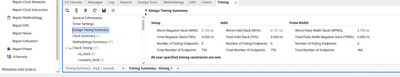
Taking the setup WNS value from here, \(F_{\text{max}} \approx \frac{1000}{T_{\text{clock}} - \text{WNS_Setup}}\)=205.34 MHz. Congratulations !! We have achieved improvement of performance from 187.23 MHz to 205.34 MHz.
Area Optimization
Since we reduced the size of both the priority encoder and the STDP LUT, let us see the impact from Vivado utilization report for the optimized learning engine :
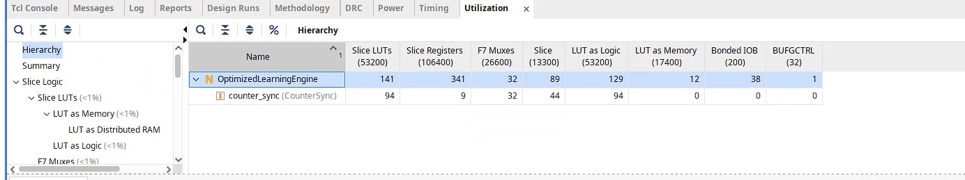
We can see the resource usage reduced to only 141 LUTs from 179 and to 341 Registers from 347 !! Certainly a signficant percentage of resource savings !! Thus we have also achieved Area optimization !!
Power Optimization
The savings in resources will also result into reduced power consumption as shown by the Vivado power report below :
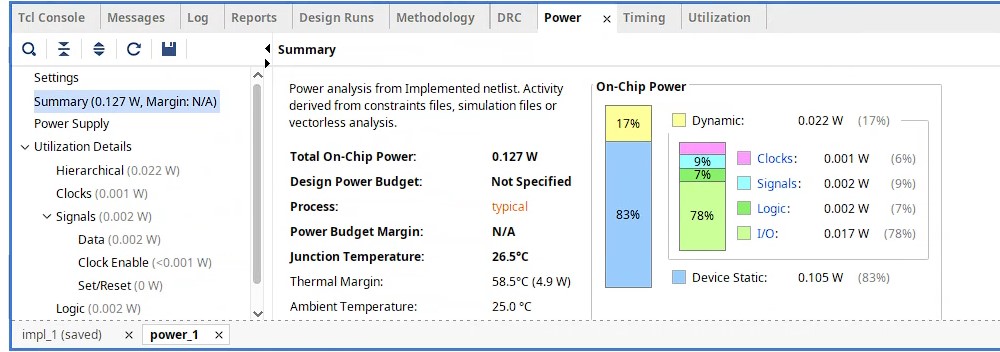
We can see the total power consumption has reduced to 127 mw from 129 mw due to reduction in dynamic power usage. Thus, it confirms our achievent in power optimization.
Congratulations !! We achieved PPA (Performance, Power and Area) optimization !!
Stay tuned for the next post, where we’ll delve deeper how we can achieve PPA optimization of the same learning engine RTL in ASIC design using legacy EDA tools !! Happy coding !!